In the ever-evolving world of electronics, high-frequency devices and systems have become indispensable in various applications, ranging from telecommunications to aerospace and defense. These high-frequency circuits operate at frequencies ranging from hundreds of megahertz to tens of gigahertz, necessitating specialized design considerations and manufacturing processes for printed circuit boards (PCBs). This article delves into the intricacies of high-frequency PCB design, materials, and manufacturing processes, providing insights into the critical aspects that ensure optimal performance and reliability.
Understanding High Frequency PCB Design
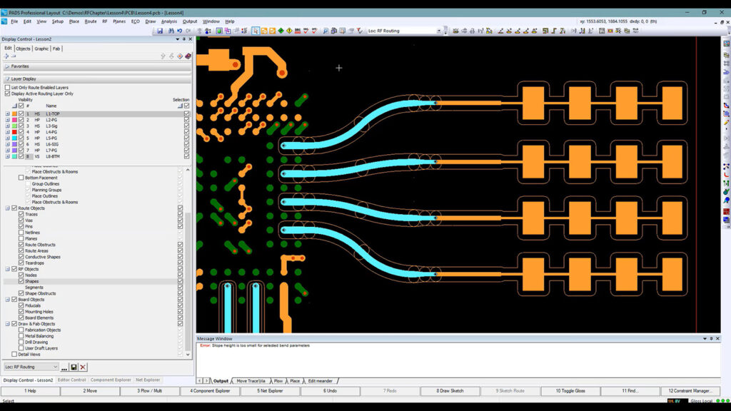
High-frequency PCB design poses unique challenges compared to traditional low-frequency designs. At these elevated frequencies, factors such as signal integrity, impedance control, and electromagnetic interference (EMI) become paramount considerations. Careful attention must be paid to every aspect of the design process to mitigate potential issues and ensure reliable circuit operation.
Signal Integrity
Signal integrity is a crucial aspect of high-frequency PCB design. High-frequency signals are susceptible to various forms of degradation, including reflections, crosstalk, and electromagnetic interference (EMI). These factors can lead to signal distortion, data corruption, and overall performance degradation.
To maintain signal integrity, designers must ensure controlled impedance routing, minimize trace lengths, and carefully manage signal transitions and terminations. Techniques such as differential pair routing, ground plane shaping, and shielding are often employed to mitigate signal integrity issues.
Impedance Control
Impedance control is a critical aspect of high-frequency PCB design. At high frequencies, the electrical characteristics of the transmission lines (traces) become significant, and any impedance mismatches can lead to signal reflections and standing waves, adversely affecting circuit performance.
Designers must carefully consider the geometry of the transmission lines, including trace width, trace spacing, and dielectric materials, to achieve the desired characteristic impedance, typically 50 ohms for high-frequency applications. Controlled impedance routing techniques, such as microstrip and stripline configurations, are employed to maintain consistent impedance throughout the signal paths.
Electromagnetic Interference (EMI)
High-frequency circuits are susceptible to both generating and receiving electromagnetic interference (EMI). EMI can lead to signal degradation, system malfunctions, and potential violations of regulatory requirements.
To mitigate EMI issues, designers must employ shielding techniques, such as the use of ground planes, guard traces, and shielded enclosures. Proper grounding and filtering strategies are also crucial to prevent EMI from propagating through the system. Additionally, adhering to layout guidelines and following best practices for component placement and routing can significantly reduce EMI susceptibility.
High Frequency PCB Materials
The choice of materials used in the construction of high-frequency PCBs is critical to achieving the desired performance and reliability. These materials must possess specific electrical, thermal, and mechanical properties to meet the stringent requirements of high-frequency applications.
Dielectric Materials
The dielectric material, also known as the substrate, plays a vital role in the performance of high-frequency PCBs. Common dielectric materials used in high-frequency applications include:
- PTFE (Polytetrafluoroethylene): PTFE-based materials, such as Rogers RT/duroid and Taconic TLX, offer low dielectric constants and low loss tangents, making them suitable for high-frequency and microwave applications.
- Hydrocarbon Ceramic Composites: Materials like Rogers RO4000 series and Isola IS680 combine hydrocarbon and ceramic components, providing a balance of electrical and mechanical properties for high-frequency applications.
- Liquid Crystal Polymer (LCP): LCP materials, such as Rogers ULTRALAM and Panasonic MEGTRON, exhibit low dielectric constants, low loss tangents, and excellent dimensional stability, making them suitable for high-frequency and millimeter-wave applications.
The selection of the dielectric material depends on factors such as the desired electrical properties, frequency range, thermal requirements, and cost considerations.
Conductive Materials
The conductive materials used in high-frequency PCBs play a crucial role in signal propagation and power distribution. Commonly used conductive materials include:
- Copper: Copper is the most widely used conductive material in PCBs due to its excellent electrical conductivity and cost-effectiveness.
- Aluminum: Aluminum is sometimes used as an alternative to copper, particularly in applications where weight is a critical factor, such as in aerospace and defense applications.
- Plated materials: Electroplated materials, such as electroless nickel immersion gold (ENIG) and immersion silver, are often used as surface finishes to enhance solderability, protect against oxidation, and improve high-frequency performance.
In addition to the conductive materials, the thickness and surface roughness of the copper layers can significantly impact signal integrity and loss characteristics at high frequencies.
High Frequency PCB Manufacturing Processes

The manufacturing processes used for high-frequency PCBs differ from those employed for traditional low-frequency designs. These specialized processes are necessary to achieve the required precision, tolerances, and performance characteristics.
Lamination and Layup
The lamination process involves bonding multiple layers of dielectric material and conductive layers (copper foils) together under high temperature and pressure. This process is critical for ensuring the dimensional stability and integrity of the final PCB.
In high-frequency PCB manufacturing, special attention is given to the layup process, which involves precisely aligning and stacking the various layers of dielectric and conductive materials. This ensures proper registration and minimizes potential misalignments that could adversely affect signal integrity and impedance control.
Drilling and Via Formation
Drilling and via formation are essential steps in the manufacturing process of high-frequency PCBs. Vias are conductive pathways that connect different layers of the PCB, facilitating signal and power distribution.
In high-frequency PCB manufacturing, specialized drilling techniques, such as laser drilling and controlled depth drilling, are often employed to achieve precise via geometries and minimize potential signal degradation. Additionally, techniques like via shielding and backdrilling may be used to mitigate signal integrity issues and improve high-frequency performance.
Metallization and Plating
Metallization and plating processes are crucial for ensuring reliable electrical connections and enhancing the performance of high-frequency PCBs. These processes involve depositing conductive materials, such as copper or precious metals, onto the surfaces of the PCB.
Techniques like electroless copper deposition, electrolytic copper plating, and immersion tin or gold plating are commonly used in high-frequency PCB manufacturing. These processes must be tightly controlled to achieve the desired layer thicknesses, surface finishes, and electrical properties required for high-frequency applications.
Testing and Verification
Due to the stringent performance requirements of high-frequency PCBs, thorough testing and verification processes are essential. These processes may include electrical testing, impedance measurement, and signal integrity analysis to ensure compliance with design specifications and industry standards.
Advanced testing techniques, such as time-domain reflectometry (TDR) and vector network analysis (VNA), are often employed to characterize the high-frequency performance of the PCBs and identify potential issues or anomalies.
Comparison Table: High Frequency PCB Materials
To aid in the selection of suitable materials for high-frequency PCB applications, we’ve provided a comparison table highlighting the key properties of commonly used dielectric materials:
| Material | Dielectric Constant (Dk) | Loss Tangent (Df) | Thermal Conductivity (W/m-K) | Typical Applications |
|---|---|---|---|---|
| PTFE (Rogers RT/duroid) | 2.1 – 2.2 | 0.0003 – 0.0005 | 0.2 – 0.3 | High-frequency and microwave circuits, antennas |
| Hydrocarbon Ceramic Composite (Rogers RO4000 series) | 3.38 – 3.66 | 0.0023 – 0.0037 | 0.69 – 0.71 | Wireless communications, radar systems |
| Liquid Crystal Polymer (Rogers ULTRALAM) | 2.9 – 3.0 | 0.0018 – 0.0024 | 0.78 | Millimeter-wave and high-speed digital applications |
| Hydrocarbon Ceramic Composite (Isola IS680) | 3.8 | 0.0035 | 0.8 | High-frequency and microwave applications |
| Woven Glass Reinforced Hydrocarbon (Arlon AD1000) | 3.0 | 0.0018 | 0.4 | High-frequency and microwave applications |
It’s important to note that the selection of the dielectric material should be based on a comprehensive evaluation of the application requirements, including frequency range, power levels, thermal management needs, and cost considerations.
Frequently Asked Questions (FAQs)

- What is the significance of controlled impedance routing in high-frequency PCB design? Controlled impedance routing ensures that the characteristic impedance of the transmission lines (traces) is maintained at the desired value, typically 50 ohms for high-frequency applications. This minimizes signal reflections and ensures proper signal propagation, which is crucial for maintaining signal integrity at high frequencies.
- Why is shielding important in high-frequency PCB design? Shielding is essential in high-frequency PCB design to mitigate electromagnetic interference (EMI) issues. Shielding techniques, such as the use of ground planes, guard traces, and shielded enclosures, help contain electromagnetic emissions and prevent external interference from affecting sensitive circuits.
- What is the role of dielectric materials in high-frequency PCB performance? Dielectric materials, or substrates, play a vital role in the performance of high-frequency PCBs. Their electrical properties, such as dielectric constant and loss tangent, significantly impact signal propagation, losses, and overall circuit performance at high frequencies. The choice of dielectric material depends on factors like frequency range, electrical requirements, and thermal management needs.
- Why are specialized manufacturing processes necessary for high-frequency PCBs? High-frequency PCBs require specialized manufacturing processes to achieve the necessary precision, tolerances, and performance characteristics. Techniques like precise layup, controlled depth drilling, via shielding, and advanced metallization processes are employed to ensure signal integrity, impedance control, and reliable high-frequency operation.
- How is testing and verification conducted for high-frequency PCBs? Testing and verification processes for high-frequency PCBs involve various techniques, such as electrical testing, impedance measurement, and signal integrity analysis. Advanced testing methods like time-domain reflectometry (TDR) and vector network analysis (VNA) are often employed to characterize the high-frequency performance and identify potential issues or anomalies.
By understanding the design considerations, material selection, and manufacturing processes specific to high-frequency PCBs, engineers can develop reliable and high-performing circuits that meet the demanding requirements of modern high-frequency applications. Careful attention to these aspects is crucial for achieving optimal signal integrity, EMI mitigation, and overall system performance in the high-frequency domain.
No responses yet