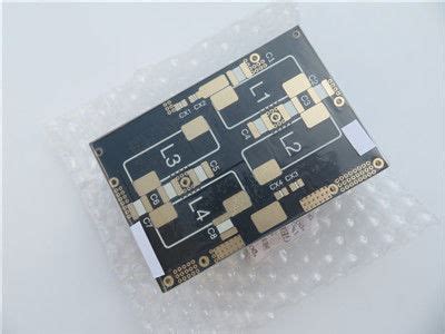
Characteristics of PTFE PCB
Dielectric Properties
PTFE boasts excellent dielectric properties, making it an ideal substrate for high-frequency applications. Its low dielectric constant (Dk) and dissipation factor (Df) ensure minimal signal loss and distortion, even at high frequencies. The table below compares the dielectric properties of PTFE with other common PCB substrate materials:
| Material | Dielectric Constant (Dk) | Dissipation Factor (Df) |
|---|---|---|
| PTFE | 2.1 | 0.0002 |
| FR-4 | 4.5 | 0.02 |
| Rogers | 3.5 | 0.0037 |
Thermal Stability
PTFE PCBs exhibit exceptional thermal stability, with a continuous operating temperature range of -200°C to +260°C. This wide temperature range makes them suitable for applications in extreme environments, such as aerospace and military equipment. The thermal expansion coefficient of PTFE is also very low, minimizing the risk of thermal stress and warpage during temperature fluctuations.
Chemical Resistance
PTFE is highly resistant to most chemicals, including acids, bases, and solvents. This chemical inertness prevents the PCB from degrading or corroding when exposed to harsh environments, ensuring long-term reliability and performance. PTFE’s non-stick properties also make it resistant to moisture absorption, further enhancing its durability.
Applications of PTFE PCB
High-Frequency Communications
PTFE PCBs are extensively used in high-frequency communication systems, such as:
- 5G networks
- Radar systems
- Satellite communications
- Microwave devices
The low dielectric constant and dissipation factor of PTFE minimize signal loss and distortion, enabling high-speed data transmission and improved signal integrity.
Aerospace and Military
The aerospace and military sectors rely on PTFE PCBs for their ability to withstand extreme temperatures, vibrations, and exposure to chemicals. Some common applications include:
- Avionics systems
- Missile guidance systems
- Satellites
- Radar equipment
PTFE’s thermal stability and chemical resistance ensure reliable performance in these critical applications, even under the most demanding conditions.
Medical Devices
PTFE PCBs are increasingly used in medical devices due to their biocompatibility and resistance to sterilization processes. Some examples include:
- Implantable devices
- Diagnostic equipment
- Surgical instruments
The non-reactive nature of PTFE prevents the PCB from causing adverse reactions when in contact with human tissue, making it a safe choice for medical applications.
Manufacturing Process of PTFE PCB
The manufacturing process of PTFE PCBs differs from that of standard FR-4 PCBs due to the unique properties of PTFE. The key steps involved are:
-
Substrate Preparation: PTFE laminates are cut to the desired size and shape, and the surfaces are cleaned to remove any contaminants.
-
Drilling: Holes are drilled into the PTFE substrate to accommodate components and vias. Special drill bits and parameters are used to prevent delamination and minimize heat generation.
-
Plating: The drilled holes are plated with copper to create electrical connections between layers. Electroless plating is commonly used for PTFE PCBs, as the non-stick surface of PTFE makes it challenging to adhere to other materials.
-
Patterning: The desired circuit pattern is transferred onto the copper-clad PTFE substrate using photolithography. A photoresist is applied, exposed, and developed to create the circuit image.
-
Etching: The exposed copper is etched away using a chemical solution, leaving behind the desired circuit pattern.
-
Solder Mask and Silkscreen: A solder mask is applied to protect the copper traces, and a silkscreen is used to add component designators and other markings.
-
Surface Finish: A surface finish, such as ENIG (Electroless Nickel Immersion Gold) or HASL (Hot Air Solder Leveling), is applied to the exposed copper to prevent oxidation and improve solderability.

Advantages of PTFE PCB
- Excellent dielectric properties for high-frequency applications
- Wide operating temperature range (-200°C to +260°C)
- High chemical resistance and moisture resistance
- Low thermal expansion coefficient, minimizing thermal stress and warpage
- Biocompatibility for medical device applications
- Suitable for applications in extreme environments
Disadvantages of PTFE PCB
- Higher material cost compared to standard FR-4 PCBs
- More complex manufacturing process, requiring specialized equipment and techniques
- Difficulty in adhering to other materials due to non-stick properties
- Limited availability of PTFE laminates in various thicknesses and copper weights
- Reduced mechanical strength compared to other PCB substrates
FAQ
1. What is the difference between PTFE and Teflon?
PTFE (Polytetrafluoroethylene) is the generic name for the synthetic fluoropolymer, while Teflon is a brand name for PTFE products manufactured by Chemours (formerly DuPont).
2. Can PTFE PCBs be used for high-power applications?
Yes, PTFE PCBs can be used for high-power applications due to their excellent thermal stability and low thermal expansion coefficient. However, proper thermal management techniques must be employed to ensure reliable performance.
3. Are PTFE PCBs more expensive than standard FR-4 PCBs?
Yes, PTFE PCBs are generally more expensive than standard FR-4 PCBs due to the higher cost of PTFE laminates and the more complex manufacturing process required.
4. Can PTFE PCBs be recycled?
PTFE PCBs can be recycled, but the process is more challenging compared to standard FR-4 PCBs. The recycling process involves separating the PTFE substrate from the copper and other components, which requires specialized equipment and techniques.
5. What are some alternatives to PTFE PCBs for high-frequency applications?
Some alternatives to PTFE PCBs for high-frequency applications include:
- Rogers PCBs: Made from high-frequency laminates such as RO3003 and RO4350B
- Hybrid PCBs: Combine PTFE and FR-4 substrates for cost-effective high-frequency performance
- Ceramic PCBs: Offer excellent high-frequency performance but at a higher cost than PTFE PCBs
In conclusion, PTFE PCBs are a specialized type of printed circuit board that offer exceptional electrical, thermal, and chemical properties. Their low dielectric constant, wide operating temperature range, and high chemical resistance make them ideal for high-frequency, high-speed, and high-temperature applications in various industries. While PTFE PCBs come with a higher cost and more complex manufacturing process compared to standard FR-4 PCBs, their unique characteristics make them an indispensable choice for demanding applications in telecommunications, aerospace, military, and medical devices.

No responses yet